Rapid Prototyping
Use this manufacturing process to evaluate a design before the next iteration.
Explore prototyping ↗
Precision starts with the right process. Explore CNC machining for custom metal and engineering plastic components, from prototypes to repeat production.
Prepare a project inquiry ↗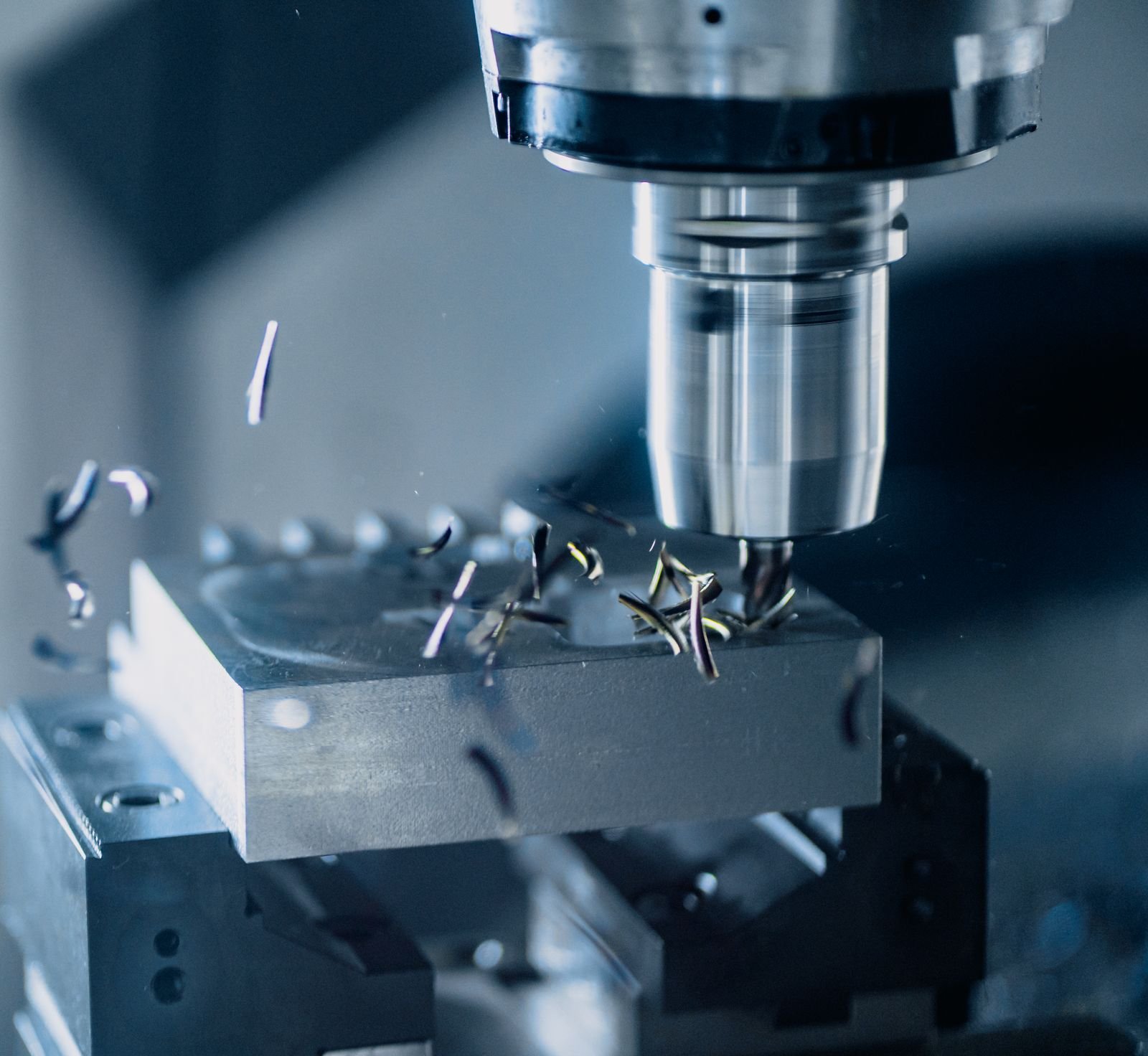
CNC machining removes material from solid stock using computer-controlled cutting tools. It is well suited to functional parts where material performance and accurately defined features matter.
For prismatic parts, pockets, mounting features and contoured surfaces. Tool access and workholding affect the machining approach.
For rotational parts such as shafts, bushings and threaded components. Provide diameters, fits and concentricity requirements.
Use a controlled drawing revision to move from design validation toward repeatable batches. Agree inspection and finishing before production.
Aluminum 6061 / 7075, stainless steel 304 / 316, brass, steel, POM and other engineering plastics — confirm grade availability.
As-machined, bead blasting, anodizing and plating options for review. Finishing may affect fit and dimensions.
Material grade, finish availability and inspection scope are confirmed during quotation.
| Protolabs benchmark | Published reference — not Winston Rapid capacity |
|---|---|
| Fast-turn headline | Protolabs advertises selected prototypes in as little as 1 day; expanded automated milling is separately promoted at 4 days. |
| Factory milling envelope | 559 × 356 × 95.3 mm; material-dependent. |
| No-drawing factory milling tolerance | ±0.127 mm. |
| Factory turning envelope | Diameter 100.33 mm; length 228.6 mm. |
| Winston Rapid machines / monthly output | Not yet confirmed; no Protolabs CNC machine-count figure is reused. |
Source: Protolabs official cnc information ↗ · Reference only; not a Winston Rapid promise.
Avoid unnecessarily deep pockets, thin walls and sharp internal corners. Identify datum surfaces, threads and tight-tolerance features.
STEP or IGES plus a dimensioned PDF drawing for tolerances, threads and surface requirements.
State quantity, intended use, critical dimensions, visible surfaces, destination and target date. Identify your drawing revision.
Brackets · housings · shafts · fixtures. Final process selection depends on geometry, material, performance and quantity.
STEP or IGES plus a dimensioned PDF drawing for tolerances, threads and surface requirements. Include quantities, finishing, inspection requirements and shipping destination.
No. The current capacity profile contains clearly marked planning examples. Firm manufacturing commitments are made only after technical review and quotation approval.
Use the inquiry form to submit your project requirements. Submit your requirements and CAD files using the project inquiry form.
Use this manufacturing process to evaluate a design before the next iteration.
Explore prototyping ↗Review this process for smaller batches and repeat parts.
Explore production ↗Prepare geometry, drawings and acceptance criteria.
Read design guides ↗Review grade, finish and functional priorities.
Explore materials ↗Build a clearer brief around the application.
Explore applications ↗Milling is suitable for pockets, faces, slots and contoured features. Turning suits shafts, bushings and other rotational components. Parts combining both may require multiple setups.
Identify datums, fits, threads, surface roughness and dimensions requiring inspection on a PDF drawing. Specify whether you need dimensional reports or material documentation.
Discuss anodizing, blasting or plating before manufacture. Coating thickness, masking and cosmetic surfaces can change machining allowances and acceptance criteria.
Send STEP or IGES files, a revision-controlled drawing, material grade, quantities, finish, shipping destination and target date. Machine envelope, achievable tolerance and lead time are confirmed after review.